")
Electrical CADD Workflow in AutoCAD Electrical: A Complete Lifecycle Approach to Precision-Driven Control System Design
Electrical design today demands far more than neatly drafted schematics. Engineers must deliver intelligent documentation that connects logic, hardware, installation, procurement, and long-term maintenance into one coordinated system. This is where a structured Electrical CADD Workflow Design becomes essential. Instead of treating drafting as a sequence of disconnected drawings, professionals follow a lifecycle approach that integrates configuration, schematic development, component management, panel layout, reporting, and revision control into a unified environment.
Electrical CADD Workflow Design
AutoCAD Electrical provides specialized tools tailored specifically for electrical engineers and control system designers. However, software efficiency depends entirely on how well teams structure their workflow. A disciplined Electrical CADD Workflow Design Electrical reduces design errors, accelerates execution, improves collaboration, and ensures compliance with industry standards. This comprehensive guide explores the complete process in fourteen detailed sections, each explaining how to build a reliable, scalable, and high-performance workflow from concept to final documentation.
1. Strategic Planning: The Starting Point of an Effective Electrical CADD Workflow in AutoCAD Electrical
Every successful electrical project begins with structured planning. Before opening any drawing file, engineers must clearly define project scope, system voltage levels, safety classifications, client specifications, and regulatory standards. This foundational step shapes the entire Electrical CADD Workflow in AutoCAD Electrical.
When teams establish naming conventions, wire numbering logic, device tagging formats, and drawing organization methods at the outset, they prevent confusion during later stages. Additionally, aligning stakeholders early ensures that documentation matches installation requirements.
Planning also includes identifying applicable standards such as IEC, ANSI, or company-specific guidelines. By creating a roadmap before drafting begins, engineers minimize rework and maintain consistency throughout the project lifecycle.
2. Project Creation and Intelligent Configuration
Once planning concludes, designers initiate the project within AutoCAD Electrical. The Electrical CADD Workflow Design Electrical relies on project files that group all related drawings into a single structured environment. This centralized approach enables seamless coordination between schematics, panel layouts, and reports.
During configuration, designers define:
-
Drawing templates and borders
-
Title block attributes
-
Layer standards
-
Wire numbering formats
-
Cross-referencing behavior
-
Component tagging rules
Templates play a crucial role in accelerating setup. Instead of redefining layers or properties repeatedly, teams preload standard settings into reusable templates. As a result, new projects begin with consistent configurations.
Moreover, adding metadata such as client information and revision notes improves documentation clarity. A properly configured project environment prevents structural issues later in the workflow.
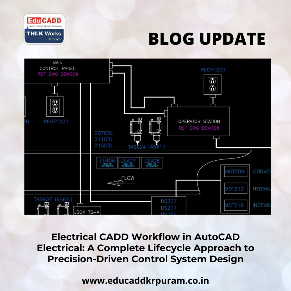
3. Structured Schematic Design Development
Schematic drawings represent the logical foundation of any control system. Within the Electrical CADD Workflow in AutoCAD Electrical, designers use intelligent symbol libraries rather than generic blocks. These symbols contain built-in attributes such as part numbers, ratings, and descriptions.
Engineers construct ladder diagrams, motor control circuits, and distribution systems using standardized components. Because these symbols are intelligent, the software automatically manages relationships between coils and contacts, reducing manual coordination.
Additionally, rung numbering and wire connectivity adjust dynamically when circuits change. This automation allows engineers to focus on functional accuracy instead of repetitive drafting tasks.
Clear schematics serve as essential references for installation, commissioning, and troubleshooting. Therefore, maintaining clarity and logical organization remains critical.
4. Intelligent Component Tagging and Data Consistency
Precise identification strengthens the Electrical CADD Workflow Design Electrical. Each inserted component must carry a unique tag that follows predefined rules. The software allows designers to configure tag formats based on project requirements.
For example, motors may follow a structured naming pattern such as MTR-01, while breakers may use CB-101. Since the system assigns tags automatically, duplication rarely occurs.
Beyond tagging, attribute management tools simplify bulk editing. Designers can update manufacturer details or descriptions across multiple components simultaneously.
This structured data management enhances traceability and ensures that reports reflect accurate information. Consistency in tagging supports both engineering accuracy and procurement efficiency.
5. Automated Wire Numbering for Accuracy and Clarity
Wire numbering plays a critical role in electrical documentation. A disciplined Electrical CADD Workflow in AutoCAD Electrical eliminates manual numbering and replaces it with automated logic-based systems.
Designers configure numbering methods according to project standards. Options include sequential numbering or reference-based numbering tied to drawing locations. Once configured, wires receive numbers instantly as they are drawn.
If modifications occur, the software updates numbering automatically. This dynamic adjustment prevents duplication and confusion during installation.
Accurate wire numbering simplifies troubleshooting and supports panel wiring accuracy. By standardizing this process, teams enhance reliability and reduce field errors.
6. PLC Module Integration and I/O Coordination
Programmable logic controllers drive modern automation systems. Integrating them efficiently forms a vital part of the Electrical CADD Workflow in AutoCAD Electrical. Instead of drafting each I/O terminal manually, engineers can insert predefined PLC modules directly from libraries.
The system supports spreadsheet imports for large I/O configurations. This feature significantly reduces drafting time and improves consistency across drawings.
When I/O assignments change, updates reflect throughout associated schematics. This synchronization eliminates discrepancies between documentation and hardware.
By leveraging PLC tools effectively, designers improve productivity while maintaining high levels of accuracy.
7. Transitioning from Logical Schematics to Physical Panel Layouts
After completing schematic development, engineers move to panel layout creation. The Electrical CADD Workflow in AutoCAD Electrical maintains connections between schematic symbols and their corresponding panel footprints.
Designers insert panel components using linked data from schematics. This integration ensures consistency between logical design and physical assembly.
During layout planning, engineers consider spacing, heat management, accessibility, and wiring pathways. Clear labeling and organized arrangement improve fabrication efficiency.
Because schematic changes propagate to panel layouts, the workflow remains synchronized. This coordination reduces mismatches and enhances overall design integrity.
8. Terminal Strip Management and Cable Organization
Terminal strips connect internal components to field devices. Managing them effectively is essential within the Electrical CADD Workflow in AutoCAD Electrical. The terminal strip editor allows systematic assignment of terminals and jumper configurations.
Cable management tools further improve organization by mapping cores to terminal points. Designers can generate cable schedules automatically without relying on external spreadsheets.
This automation minimizes human error and accelerates documentation preparation. Additionally, spare terminal tracking supports future expansion planning.
Organized terminal planning enhances installation clarity and operational reliability.
9. Comprehensive Automated Reporting
Documentation accuracy directly impacts procurement and fabrication processes. The Electrical CADD Workflow in AutoCAD Electrical includes powerful reporting features that extract real-time data from drawings.
Engineers can generate:
-
Bills of materials
-
Component summaries
-
Wire lists
-
From-to connection reports
-
PLC I/O lists
Because reports remain linked to drawing data, updates occur automatically whenever modifications are made. This dynamic connection ensures consistency across all documentation.
Procurement teams rely on these reports for accurate ordering, while technicians use them during assembly and commissioning. Automated reporting streamlines coordination across departments.
10. Quality Assurance and Error Detection
Quality control safeguards project success. A robust Electrical CADD Workflow in AutoCAD Electrical incorporates regular validation checks to detect inconsistencies early.
Built-in audit tools identify duplicate tags, missing cross-references, and unused components. By resolving issues during design stages, engineers prevent costly field-level corrections.
Revision tracking features further enhance transparency. Each change can be documented systematically, maintaining accountability and version control.
Proactive error detection transforms drafting into a controlled engineering process rather than a reactive correction cycle.
11. Collaboration and Multi-User Project Management
Large-scale projects often involve multiple engineers working simultaneously. The Electrical CADD Workflow in AutoCAD Electrical supports collaborative environments through centralized project management.
Shared libraries ensure uniform symbol usage, while file locking mechanisms prevent accidental overwrites. Designers can work on separate drawings within the same project without conflicts.
Furthermore, integration with other design platforms enhances interdisciplinary coordination. Clear communication combined with structured file management strengthens overall project efficiency.
Effective collaboration reduces delays and supports smooth project delivery.
12. Standardization Through Custom Libraries and Templates
Organizations benefit greatly from establishing standardized resources. Within the Electrical CADD Workflow in AutoCAD Electrical, custom symbol libraries and reusable templates streamline future projects.
Companies can create predefined component libraries with accurate attributes and footprints. Similarly, project templates can include preferred numbering schemes, title blocks, and report configurations.
Standardization reduces repetitive setup work and ensures consistent documentation across all projects. Over time, these resources become valuable operational assets.
Consistency not only improves efficiency but also strengthens brand professionalism.
13. Advanced Productivity Tools and Workflow Optimization
AutoCAD Electrical includes advanced features that enhance the Electrical CADD Workflow in AutoCAD Electrical. Circuit copying tools allow designers to replicate complex configurations quickly while maintaining cross-references.
Signal arrow utilities simplify multi-drawing connections. Parametric footprint builders ensure accurate panel representations.
Continuous training ensures that teams maximize these advanced capabilities. As software evolves, staying updated allows organizations to maintain competitive advantage.
Small workflow improvements can produce significant time savings across large engineering projects.
14. Embracing the Future of Digital Electrical Engineering
Electrical design continues to evolve alongside Industry 4.0 technologies. The Electrical CADD Workflow in AutoCAD Electrical now integrates with digital manufacturing systems, cloud collaboration platforms, and data analytics tools.
Data-rich drawings support predictive maintenance systems and digital twin development. As automation expands, structured documentation becomes even more critical.
Engineers who master disciplined workflows today position themselves for future innovation. By combining automation tools with strategic planning, they create scalable and future-ready design environments.
The evolution of electrical engineering depends on structured processes that prioritize clarity, integration, and intelligent automation.
Conclusion
A structured Electrical CADD Workflow Design Electrical transforms electrical drafting into a high-precision engineering discipline. From project planning and configuration to schematic development, panel layout, reporting, and quality assurance, each stage plays a vital role in ensuring project success.
By embracing automation, enforcing standards, and maintaining collaborative coordination, engineers reduce errors and accelerate delivery timelines. As industries move toward smarter and more connected systems, mastering an organized workflow becomes essential.
Professionals who implement a disciplined Electrical CADD Workflow in AutoCAD Electrical not only improve efficiency but also elevate the overall quality and reliability of their electrical design projects.

