")
Beyond the Mesh: Mastering STL to Solid Model Conversion for Accurate CAD Engineering
In today’s fast-evolving engineering landscape, digital models drive innovation, manufacturing, and product development. Among the various file formats used in 3D design, STL files have become the industry standard for 3D printing, scanning, and rapid prototyping. However, while STL models effectively represent object geometry, they lack the intelligence and flexibility required for advanced engineering tasks. This limitation has increased the importance of STL to Solid Conversion Techniques, which enable engineers to transform mesh-based files into fully editable CAD models. These conversion methods help professionals modify designs, perform simulations, create manufacturing documentation, and improve product performance.
STL to Solid Conversion
As industries continue adopting reverse engineering and digital manufacturing practices, the need for accurate conversion solutions grows stronger. Whether recreating obsolete components, refining scanned prototypes, or preparing designs for production, solid model conversion has become a critical step in modern engineering workflows. Understanding how these techniques work allows organizations to improve efficiency, reduce redesign efforts, and maximize the value of digital assets.
Understanding the Structure of STL Files
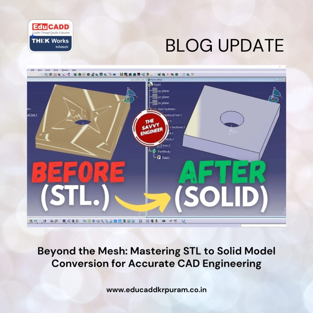
STL files represent three-dimensional objects using a network of interconnected triangles. Each triangle defines a small segment of the object’s surface, and together these facets create the overall geometry. Because STL files focus solely on shape representation, they are highly effective for applications such as additive manufacturing and visual inspection.
Despite their usefulness, STL files do not store engineering intelligence. Information such as dimensions, feature history, constraints, and parametric relationships is absent. As a result, making modifications within traditional CAD software becomes extremely difficult. Engineers often need editable models that support design changes and detailed analysis. Therefore, STL to Solid Conversion Techniques serve as a bridge between simple mesh geometry and sophisticated engineering models that can support product development activities.
The Growing Importance of Conversion in Engineering Workflows
Engineering teams frequently encounter STL files generated through 3D scanning, reverse engineering projects, and additive manufacturing processes. While these files provide valuable geometric information, they are often unsuitable for tasks requiring precise design control. Converting mesh files into solid models allows engineers to integrate scanned data into existing design workflows and perform advanced operations.
Solid models offer greater flexibility for design modifications, finite element analysis, and manufacturing preparation. Furthermore, organizations can use converted models to reproduce legacy components, improve product quality, and accelerate innovation. As businesses seek to shorten development cycles and reduce costs, efficient conversion processes have become increasingly important across multiple industrial sectors.
Preparing Mesh Data Before Starting the Conversion Process
The quality of a final solid model depends heavily on the condition of the original STL file. Many mesh models contain defects that can interfere with successful conversion. Common issues include holes, overlapping surfaces, duplicate triangles, and irregular mesh structures. These imperfections often result from scanning errors or poor file generation practices.
Before conversion begins, engineers typically repair and optimize the mesh. Specialized software tools help identify damaged regions, close gaps, smooth surfaces, and remove redundant geometry. Proper mesh preparation improves processing efficiency and reduces reconstruction errors. In addition, a clean mesh enables software algorithms to interpret geometric relationships more accurately, leading to higher-quality solid models that better represent the original object.
Direct Mesh-to-Solid Conversion Methods
One of the most widely used approaches involves direct mesh-to-solid conversion. Modern CAD systems include tools capable of transforming closed mesh bodies into solid geometry with minimal user intervention. This method is often preferred when working with relatively simple parts that contain manageable levels of detail.
Direct conversion offers several benefits. It reduces modeling time, simplifies workflows, and enables users to obtain usable solid models quickly. However, highly detailed STL files can generate complex solid bodies that remain difficult to edit. Although direct conversion may not always produce ideal engineering models, it provides an efficient starting point for many projects. Engineers often combine this approach with additional refinement techniques to improve usability and accuracy.
Surface Reconstruction for Enhanced Model Quality
Surface reconstruction is one of the most advanced STL to Solid Conversion Techniques available today. Instead of converting individual triangles directly, this process creates smooth mathematical surfaces that closely follow the original mesh geometry. These surfaces are then stitched together to form a complete solid model.
The reconstruction process begins by identifying different regions within the mesh. Engineers analyze flat surfaces, curved sections, and freeform areas separately to achieve optimal accuracy. Once the software generates appropriate surfaces, it combines them into a watertight solid body. This approach produces cleaner geometry, reduces file complexity, and significantly improves editability. Surface reconstruction is especially useful for products requiring smooth finishes and precise dimensional control.
Reverse Engineering as a Key Driver of STL Conversion
Reverse engineering has become one of the primary reasons organizations invest in conversion technologies. Many companies possess physical components without access to original design files. In such situations, engineers use 3D scanners to capture the geometry of existing parts and generate STL files.
After scanning, the mesh data undergoes conversion into a solid model that can be edited and analyzed. This workflow enables manufacturers to recreate obsolete parts, improve existing products, and maintain critical equipment. Reverse engineering also supports competitive benchmarking and product optimization initiatives. As industries increasingly rely on digital replication and modernization efforts, the connection between reverse engineering and STL conversion continues to strengthen.
Feature Recognition and Intelligent Geometry Creation
Advancements in software technology have introduced intelligent feature recognition capabilities into conversion workflows. These systems automatically identify engineering features such as holes, slots, bosses, ribs, and fillets within mesh data. Instead of manually recreating each feature, engineers can leverage automated tools to accelerate model generation.
Important advantages include:
- Reduced manual modeling effort and faster project completion.
- Improved accuracy through automatic recognition of design features.
Feature recognition helps preserve engineering intent while producing CAD models that remain easy to modify. As artificial intelligence continues advancing, automated feature detection is expected to play an even larger role in future conversion processes.
NURBS-Based Modeling for Superior Precision
Non-Uniform Rational B-Splines, commonly referred to as NURBS, represent a powerful mathematical approach to surface modeling. Unlike STL meshes, which rely on triangular approximations, NURBS surfaces define geometry using precise mathematical equations. This allows engineers to create smooth and highly accurate representations of complex shapes.
NURBS-based workflows are particularly valuable for industries requiring superior surface quality. Automotive exteriors, aerospace components, medical devices, and consumer products often rely on NURBS technology to achieve precise curvature and seamless transitions. By incorporating NURBS into STL to Solid Conversion Techniques, engineers can produce lightweight, editable models that support advanced design and manufacturing activities.
Hybrid Modeling Approaches for Complex Designs
Many real-world products contain both simple geometric features and intricate freeform surfaces. In these situations, a hybrid modeling strategy often provides the best balance between efficiency and accuracy. Rather than relying exclusively on one method, engineers combine multiple conversion techniques to address different areas of the model.
For example, planar surfaces and cylindrical features may be converted automatically, while complex sculpted regions undergo detailed surface reconstruction. This approach enables teams to achieve high-quality results without investing unnecessary effort in straightforward areas. Hybrid workflows have become increasingly popular because they offer flexibility and adaptability across a wide range of engineering applications.
Benefits of hybrid modeling include:
- Better management of mixed geometric complexity.
- Greater control over final model accuracy and performance.
Common Challenges During STL Conversion Projects
Although conversion technologies have improved significantly, engineers still encounter various challenges throughout the process. Large mesh datasets can contain millions of triangles, creating computational demands that slow software performance. In addition, scan data often includes noise, distortion, and incomplete geometry that complicate reconstruction efforts.
Another major challenge involves maintaining design intent. Simply reproducing the shape of a component is not always sufficient. Engineers must also understand how features function within the overall design. Failure to preserve functional relationships can lead to models that appear correct but perform poorly in real-world applications. Addressing these challenges requires technical expertise, careful planning, and the use of appropriate software tools.
Industrial Applications of Solid Model Conversion
The practical applications of STL conversion extend across numerous industries. Aerospace organizations use conversion workflows to recreate aging aircraft components and support maintenance operations. Automotive manufacturers rely on scanning and reconstruction technologies to analyze prototypes and optimize designs.
Medical professionals convert anatomical scan data into solid models for implant development and surgical planning. Consumer product companies accelerate innovation by transforming physical prototypes into editable digital assets. Industrial manufacturers use reverse engineering to modernize legacy equipment and improve operational efficiency. These diverse applications demonstrate the widespread value of conversion technologies in supporting modern engineering objectives.
Emerging Technologies Influencing the Future of Conversion
Technological innovation continues transforming the field of solid model conversion. Artificial intelligence and machine learning algorithms are becoming increasingly capable of recognizing geometric patterns, automating reconstruction tasks, and improving conversion accuracy. These advancements reduce manual effort while delivering more consistent results.
Cloud computing platforms also enable engineers to process massive datasets without investing heavily in local hardware infrastructure. Meanwhile, improvements in 3D scanning systems generate cleaner mesh data, simplifying downstream workflows. Together, these developments are making STL to Solid Conversion Techniques faster, smarter, and more accessible than ever before.
Best Practices for Achieving High-Quality Results
Successful conversion projects require a structured approach. Engineers should first define project objectives, accuracy requirements, and intended uses for the final model. Understanding whether the model will support manufacturing, simulation, inspection, or redesign activities helps determine the most appropriate workflow.
Regular validation against original scan data ensures dimensional consistency and reduces errors. Engineers should also avoid unnecessary complexity that can make models difficult to manage. Maintaining organized documentation and performing thorough quality checks throughout the process further improves project outcomes. By following these best practices, organizations can maximize the effectiveness of their conversion efforts and achieve reliable, repeatable results.
Conclusion
The ability to transform mesh-based STL files into intelligent CAD geometry has become a cornerstone of modern engineering and digital manufacturing. Through advanced STL to Solid Conversion Techniques, engineers can convert static scan data into fully editable models that support design optimization, simulation, quality control, and production planning. Whether using direct conversion, surface reconstruction, feature recognition, NURBS modeling, or hybrid workflows, each method contributes to creating accurate and functional engineering assets.
As industries continue embracing digital transformation, the demand for efficient conversion solutions will only increase. Organizations that master these techniques gain significant advantages in productivity, innovation, and product quality. By understanding the principles, challenges, and future trends shaping STL conversion, engineering professionals can confidently navigate the evolving world of digital design and manufacturing while unlocking new opportunities for growth and technological advancement.

