")
Precision Engineering in Practice: Hands-On GD&T Training with CAD
Engineering design demands more than theoretical knowledge—it requires accuracy, consistency, and effective communication. GD&T CAD Hands-On Training provides a standardized framework to convey design intent clearly, ensuring every engineer, manufacturer, and quality inspector interprets parts consistently.
GD&T CAD Hands-On Training
Learning GD&T in isolation can feel abstract, but pairing it with hands-on CAD practice transforms understanding into actionable skills. Applying GD&T directly to 3D models helps learners visualize tolerances, simulate assemblies, and experience the practical impact of design decisions. This combination bridges theory and real-world engineering, enhancing both learning and professional readiness.
In this article, we discuss why GD&T is essential, how CAD practice accelerates mastery, and step-by-step approaches for effective skill development.
The Role of GD&T in Modern Engineering
Traditional dimensioning techniques often fail to communicate the complete design intent. Linear measurements define size but not form, orientation, or precise relationships between features, leading to production inconsistencies and higher costs.
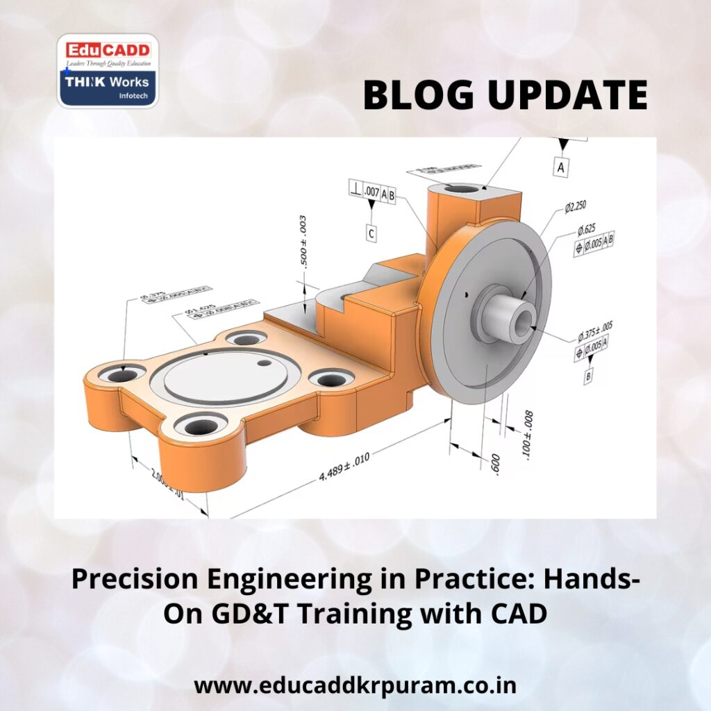
GD&T CAD Hands-On Training address these gaps. Defined by standards such as ASME Y14.5, GD&T covers five key aspects: form, profile, orientation, location, and runout. For example, instead of simply specifying a hole’s diameter, GD&T ensures the hole aligns with mating components even under manufacturing tolerances.
Industries like aerospace, automotive, robotics, and medical devices rely heavily on GD&T. Engineers trained in these principles reduce production errors, optimize assembly performance, and maintain high-quality standards. Incorporating CAD practice allows learners to apply these principles interactively, reinforcing their understanding in a real-world context.
Why CAD Practice Enhances GD&T Learning
CAD software is an essential tool for translating GD&T knowledge into practical application. Learners can annotate 3D models, define tolerance zones, and simulate part interactions.
Key benefits include:
-
Visualizing Tolerance Effects: See how deviations affect mating features.
-
Immediate Feedback: CAD highlights errors in datum selection or symbol application.
-
Hands-On Application: Practice directly on digital models rather than abstract diagrams.
-
Assembly Simulation: Test how tolerances influence overall assembly function.
-
Industry Readiness: Develop skills employers expect from engineering professionals.
Tools such as SolidWorks, CATIA, Creo, and AutoCAD integrate GD&T features, enabling interactive practice and instant validation of design decisions. Regular CAD exercises help learners internalize the principles and apply them confidently in real projects.
Understanding Core GD&T Principles
A strong foundation is essential before applying GD&T in CAD. Focus on the five main categories:
-
Form Controls: Govern shape consistency—flatness, straightness, circularity, cylindricity.
-
Profile Controls: Regulate surface contours and complex geometries.
-
Orientation Controls: Ensure proper alignment, including parallelism, perpendicularity, and angularity.
-
Location Controls: Specify exact feature placement, such as holes, slots, or pins.
-
Runout Controls: Control rotational accuracy for shafts or cylindrical components.
Datums are equally critical. Serving as reference points or surfaces, datums provide a baseline for measurements. Selecting correct datums in CAD ensures features interact as intended, improving both design accuracy and assembly reliability.
Practical Steps to Combine GD&T with CAD Learning
A structured approach enhances comprehension and skill retention:
-
Study Standards: Review ASME Y14.5 or ISO GPS to understand GD&T rules.
-
Learn Symbols: Memorize symbols, meanings, and common applications.
-
Apply to Simple Models: Start with basic shapes like blocks, cylinders, and plates.
-
Experiment with Datums: Assign references in CAD to understand their impact.
-
Simulate Assemblies: Observe how tolerances affect multi-part assemblies.
-
Perform Analysis: Use CAD tools for worst-case or statistical tolerance evaluation.
-
Progress to Complex Designs: Work on intricate parts and multi-component assemblies.
This stepwise approach ensures learners move from memorization to practical competence, preparing them for real-world engineering tasks.
Career Advantages of GD&T with CAD Expertise
Combining GD&T knowledge with CAD proficiency opens career opportunities in multiple engineering domains:
-
Manufacturing Engineers: Optimize processes and minimize production errors.
-
Quality Engineers: Verify parts against GD&T specifications using CAD-integrated tools.
-
Design Engineers: Communicate precise design intent to production teams.
-
Project Managers: Oversee projects with clear understanding of tolerance effects.
Certifications in CAD and GD&T enhance credibility, positioning learners as skilled professionals capable of designing, simulating, and inspecting components accurately. Employers value engineers who reduce rework, improve product quality, and ensure reliable assemblies.
Conclusion
Engineering precision depends on clear communication and practical application. GD&T CAD Hands-On Training define geometric standards, while hands-on CAD practice turns those standards into actionable skills.
By combining theoretical learning with CAD exercises, engineers gain the ability to visualize tolerances, validate designs, and simulate real-world assembly behavior. This integrated approach strengthens design confidence, ensures manufacturability, and enhances professional value in today’s competitive engineering landscape.
Investing in GD&T and CAD training equips learners with both knowledge and practical expertise, laying the foundation for a successful engineering career.

